-
CRT screen effect in Open Frameworks
The quality of digital displays have been changing over the years. Now, we have such quality of processing and density of pixels that we can see 4K videos at 120hz in hand-held devices. The fidelity of image is astounding.
Older screen technologies had constrains that left distinctive remarks on the image that was perceived by our eyes. In particular, the technical characteristics of CRT screens had an effect on the final image that one would see, despite what the input data represented. This is most obvious when one displays pixelated images like videogame sprites from console videogames in modern LSD and LED screens; and this is very apparent when you see the same image displayed in different types of screens, like this fantastic twitter account shows. For this particular type of art, it looses much of its appeal.
So, I wanted to see what would happen if I would to roughly imitate how the color is printed in CRT screens with code. For that reason, I wrote a simple openFrameworks program that does the following:
- Load an image and read its pixels.
- Map each color channel to a 0 to 1 interval.
- Use that interval to render an element (like a rectangle) and control characteristics of that element, like size and transparency
- Do this for each pixel.
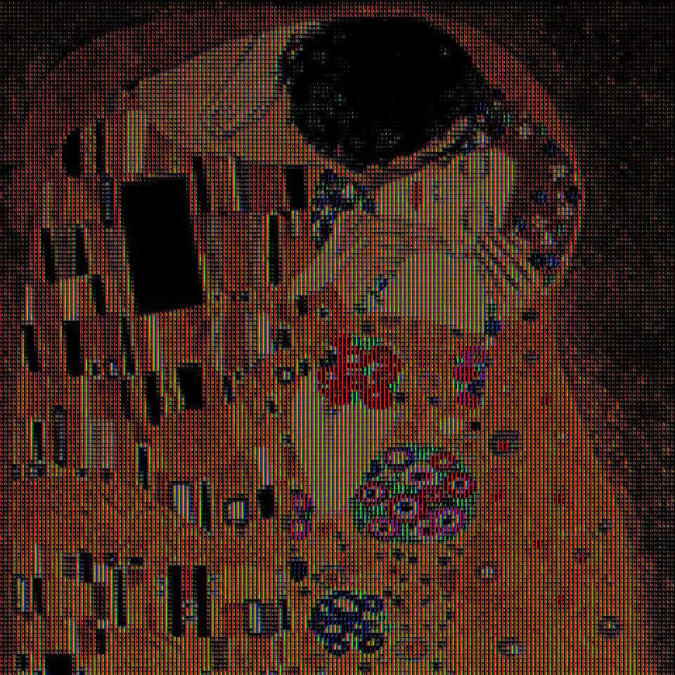
The results are actually very pleasant (click to enlarge):
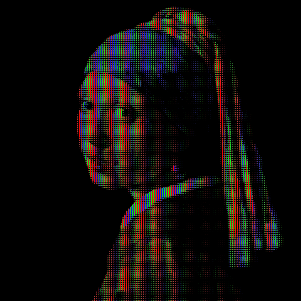
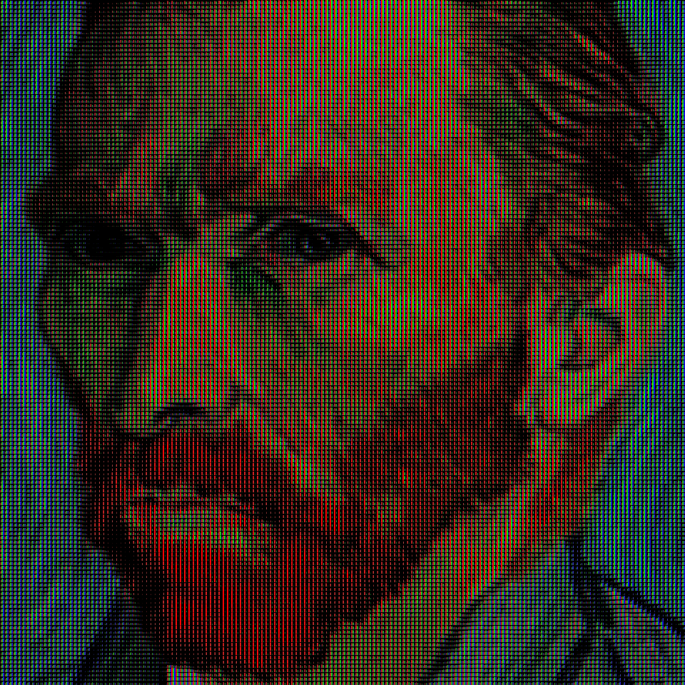

Those images are entirely comprised of red, green and blue rectangles; there are no oranges, yellows or whites.
And since I had a 0-to-1 mapping of color infomation, I could easily animate a transition between images.
I think this is a concept that can be extended and refined further to transform any kind of image and give it a bit of a retro-feel to it.
The code is in a Visual Studio 22 solution and C++, to execute you’ll need that IDE installed.
You can find a link to the code here: https://github.com/leacasas/cathodic_pixels
-
Arc gradients in Processing

Sometimes, while trying to achieve a specific result in Processing, one may need to work with color gradients. There are several different types of gradients, which usually are listed in visual editing tools like Adobe Photoshop, Illustrator and others. Those could be linear, radial, etc.
I had faced challenges when trying to style figures and shapes with color gradientes in Processing before. And in one particular instance, I needed to be able to draw arcs of different lenghts, thicknesses, radius, etc; and I also needed to style them using color gradients of more than just two colors; if possible, I should be able to set up any number of colors within that gradient, much in the same way that one would be able to do in Photoshop.
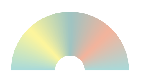
The way to achieve this in processing is leveraging the use of shapes and vertices. An arc, can be composed of a series of trapezoid-like QUADS, like the ancient romans used bricks to build arcs.

Drawing 2D shapes in Processing isn’t difficult, and one can take advantage that one is able to change the fillcolor between vertices. This way, if I could do some color interpolation, I would be able to make an arc gradient:
With this building block, I went ahead and played a little bit trying to force some compositions.


You can download and play around with the code here:
-
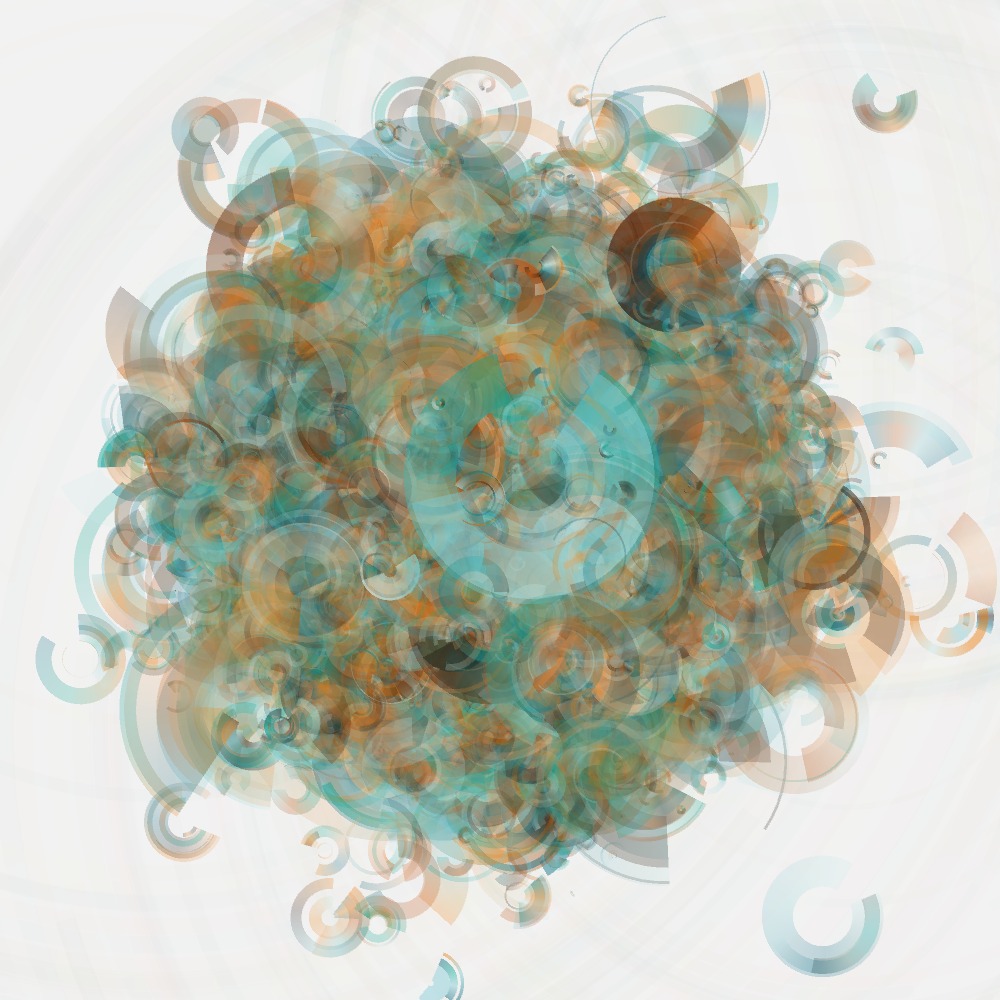
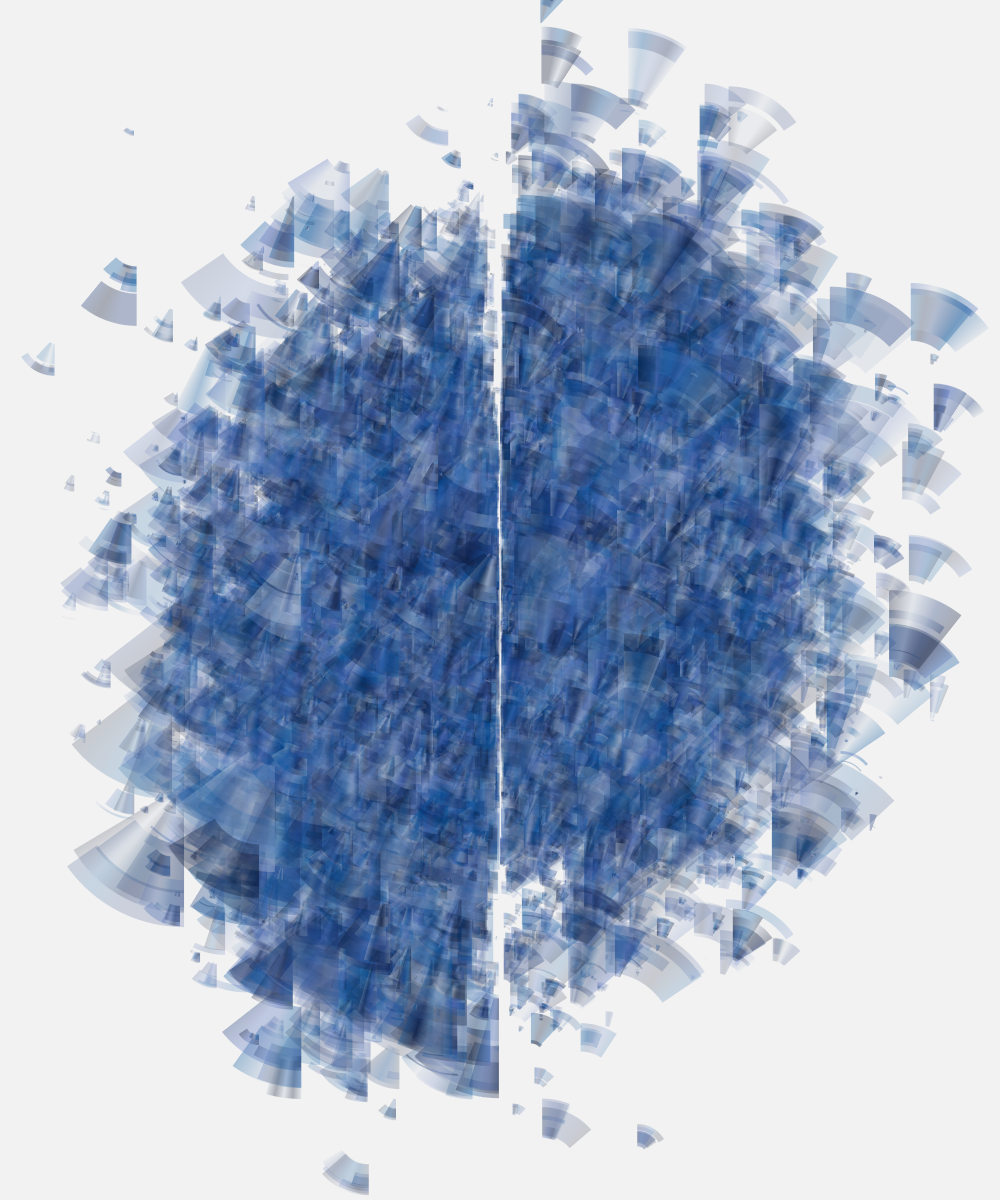
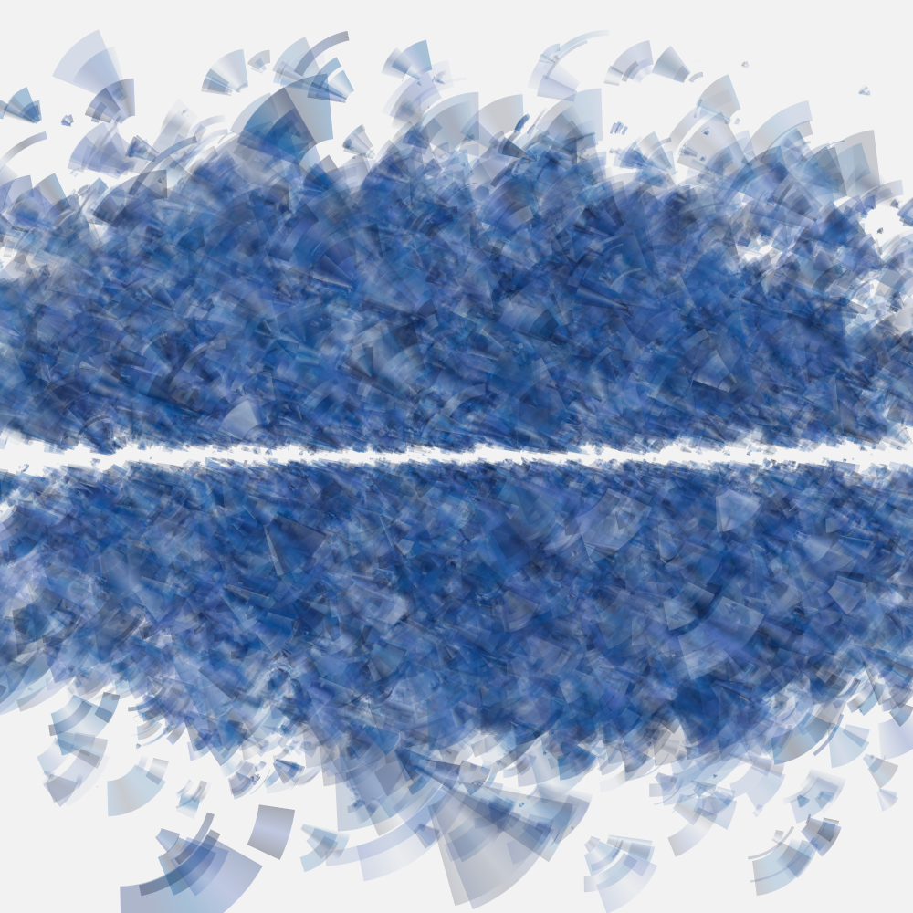
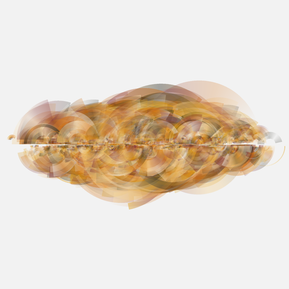
Generative Rings


Inspired by the works of Anders Hoff and Jared Tarbell, I tried to get a handle on how they (specially the latter) use subtle points to “paint” in the canvas and iteratively impress a regular pattern with just the right amount of entropy and change.
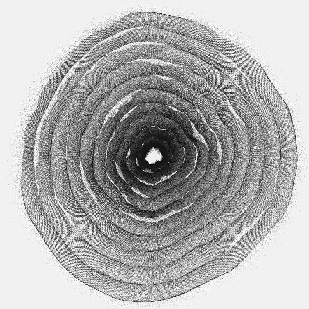
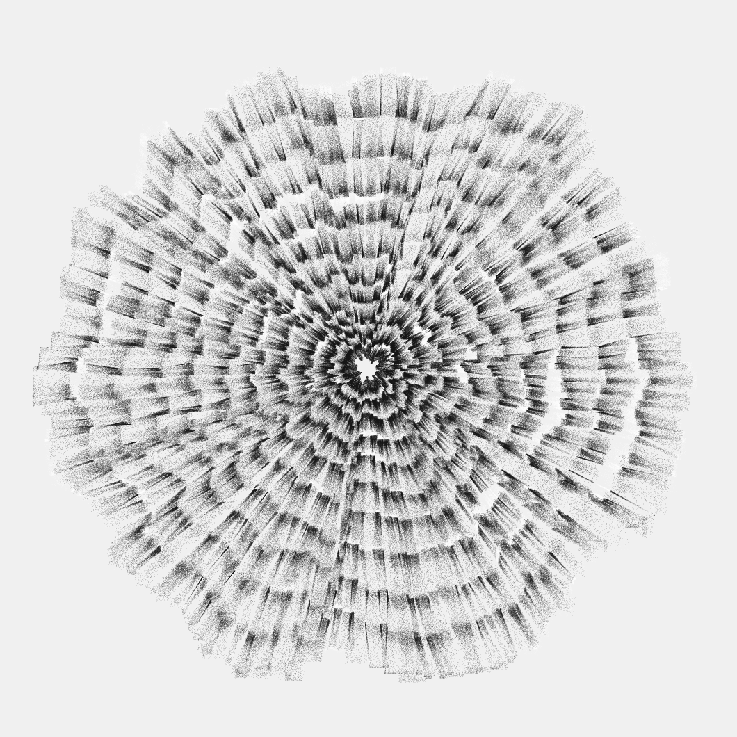
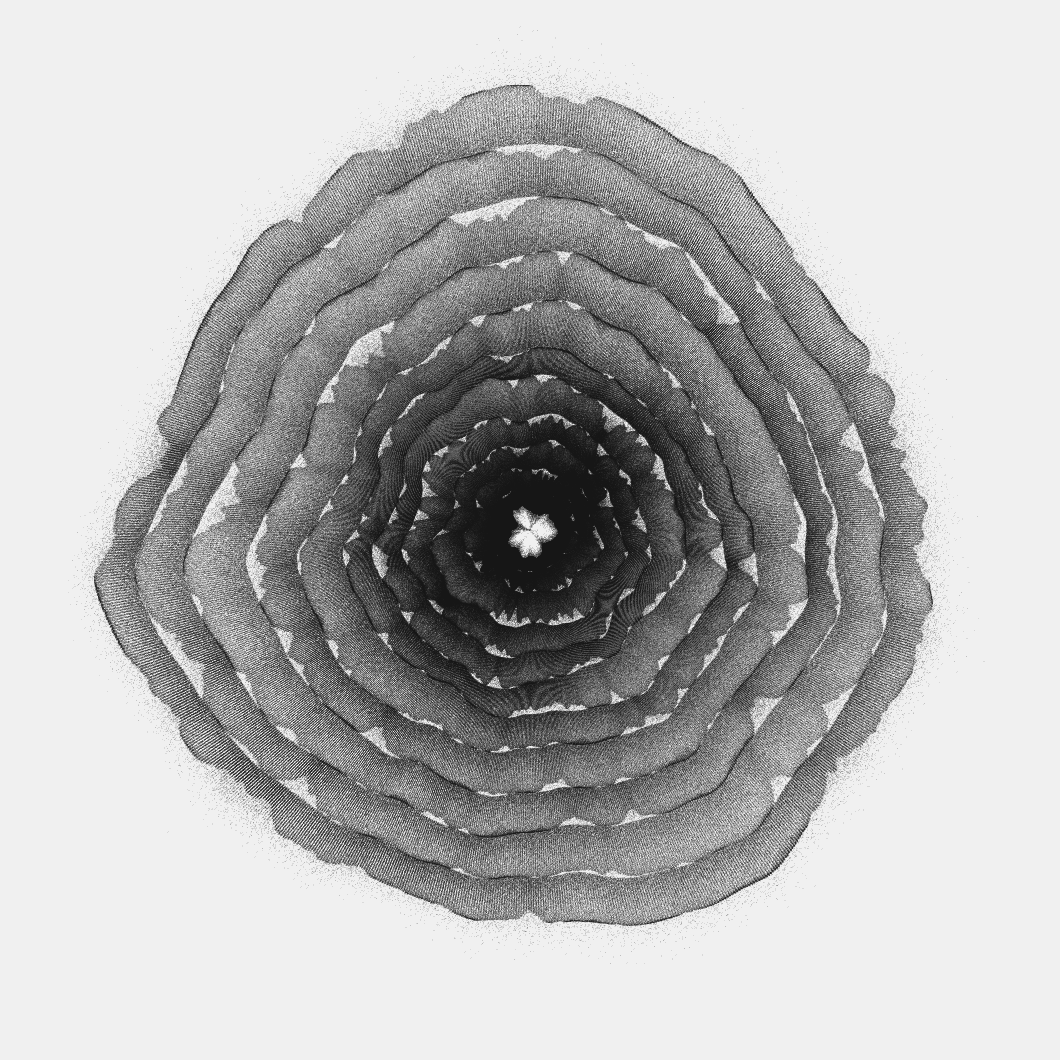
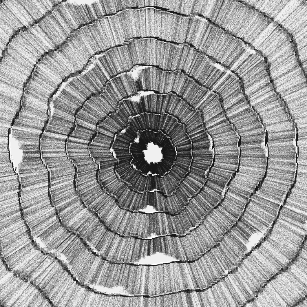
Here you can see it at work:
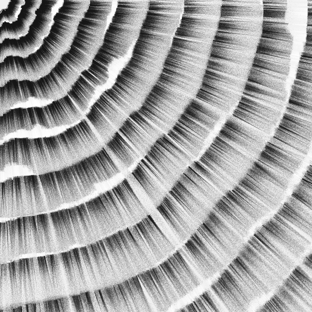
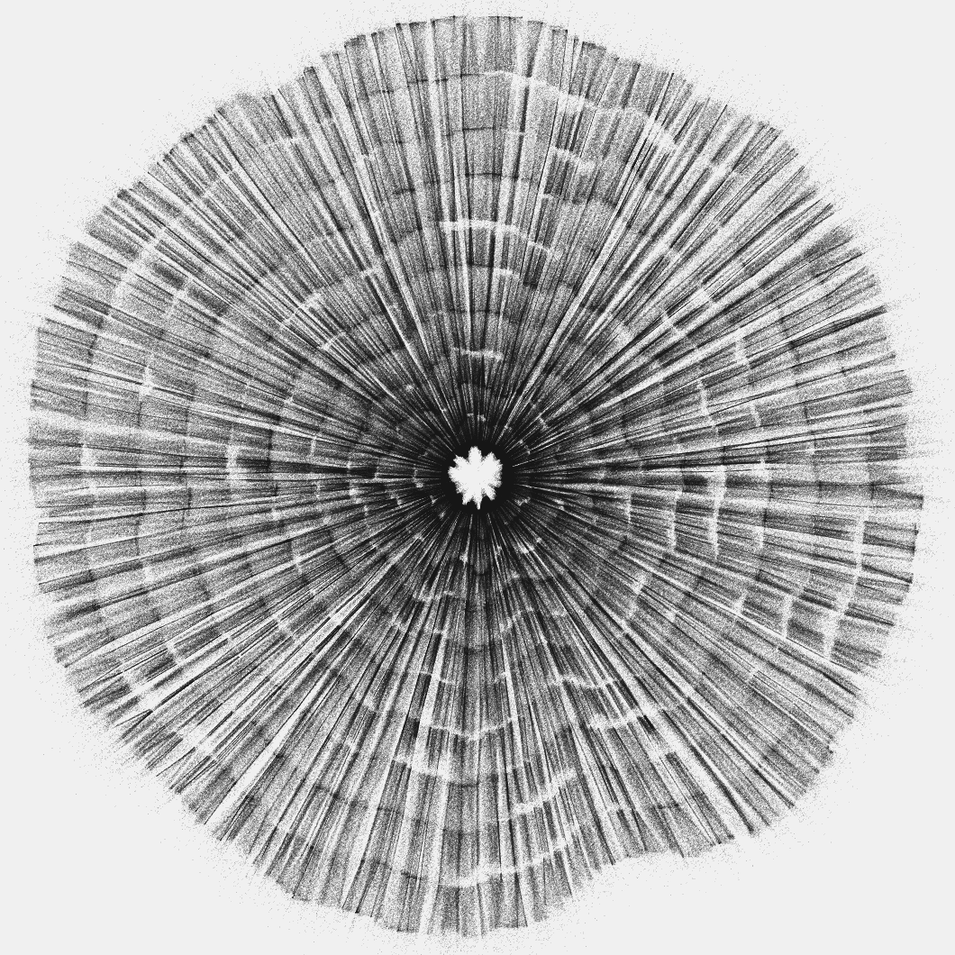
The program is quite simple: generate n number of rings where the program paints a number of black dots distributed in a thin rectangle, which moves in a circular manner around the center, introducing some variability through the use of perlin noise on the size and inclination of that rectangle.
With that same basic idea, by changing some of the parameters like width of each ring, density of the rectangles, noise, angle variability, etc; a lot of different results can be achieved with the same algorithm.
Below are more images that result from running that program:


-
Subscribe
Subscribed
Already have a WordPress.com account? Log in now.
